
Gain staging
Helps place the right amount of gain at the right point in the chain so downstream stages operate within their preferred range.
AMPLIFIERS
Microsource amplifier solutions support gain staging and signal conditioning across broad-band, medium-power, and low-noise microwave paths where a clean, controlled increase in level is needed.
Current released examples include broad-band amplifier hardware such as G-AMP-00-50-000, covering 10 MHz to 50 GHz with nominal 15 dB gain and datasheet-backed output-power, flatness, and noise performance.
Product overview
Adds controlled gain to an RF or microwave path so downstream stages see the level, margin, and interface behavior they were designed around.
Usually as part of a wider chain that includes a source, a translation stage, filtering, and packaging choices. The amplifier works best when those surrounding decisions are visible up front.
Signal conditioning
Amplifiers are often the difference between a usable chain and one that loses margin, so the gain stage has to be selected in the context of noise, flatness, and surrounding circuitry.
Gain staging that supports practical subsystem-level performance
Integration with source, translation, and conditioning stages
Options that can be adapted to the system envelope and interface requirements
A fit for situations where the amplifier is part of a larger engineered path
Final bandwidth, gain, and linearity behavior depend on the approved configuration and the full system context.
Capabilities
These pages are intentionally framed around system behavior rather than one-number marketing claims.
Helps place the right amount of gain at the right point in the chain so downstream stages operate within their preferred range.
Supports clean interface behavior when level, impedance, or bandwidth management must be considered together.
Can be paired with sources, converters, filters, and custom assemblies to support broader RF system requirements.
Packaging and interface details are typically selected around the application rather than a universal fixed housing.
If your application has a tight linearity, noise, or power budget, the amplifier should be evaluated inside the whole signal path rather than in isolation.
Applications
Amplifiers can appear in many places across the microwave chain, especially where the system needs controlled level, margin, or isolation.
Supports sensitivity and margin goals where modest gain is needed ahead of translation or detection stages.
Helps prepare drive levels for later stages in transmit or stimulus chains.
Useful for instrumentation paths that need repeatable gain behavior and clean interfaces.
Often paired with converters and filters when the full signal chain is packaged into one assembly.
Representative performance
These values are taken from supplied product data for the broad-band G-AMP-00-50-000 amplifier. They give the amplifier page a concrete reference point instead of only family-level guidance.
| Parameter | Representative value |
|---|---|
| Broad-band coverage | |
| Frequency coverage | 10 MHz to 50 GHz |
| Nominal gain | 15 dB nominal, greater than 10 dB minimum |
| Gain flatness | +/-3 dB nominal, +/-3.5 dB maximum from 10 MHz to 50 GHz |
| Output power | |
| 10 MHz to 500 MHz | +23 dBm nominal, +20 dBm minimum |
| 0.5 to 26.5 GHz | +25 dBm nominal, +23 dBm minimum |
| 26.5 to 50 GHz | +22 dBm nominal, +20 dBm minimum |
| Interfaces and limits | |
| Input / output VSWR | 2.0:1 nominal on both ports |
| Maximum load VSWR | 3:1 |
| Maximum input power | +7 dBm |
| Linearity and spectral behavior | |
| Third-order intercept | +30 dBm nominal |
| Harmonic distortion | Less than -30 dBc nominal |
| Spurious | Less than -60 dBc nominal |
| Reverse isolation | Greater than 50 dB nominal |
| Noise figure | Less than 6 dB nominal |
| Stability | Unconditionally stable |
Output power is specified as minimum saturated power into a 50 ohm load with +5 dBm input at 23 C plus or minus 5 C. Gain flatness is specified with -5 dBm input and 50 ohm load.
Measured data
Measured test data for the G-AMP-00-50-000 amplifier gives a more concrete sense of broad-band gain behavior across the published operating range.
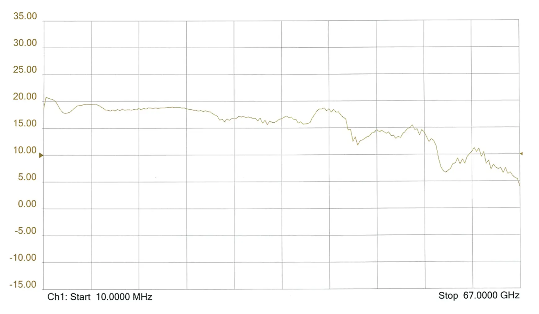
Representative test data for G-AMP-00-50-000. Final gain behavior depends on the approved configuration, test conditions, and operating setup.
Hardware
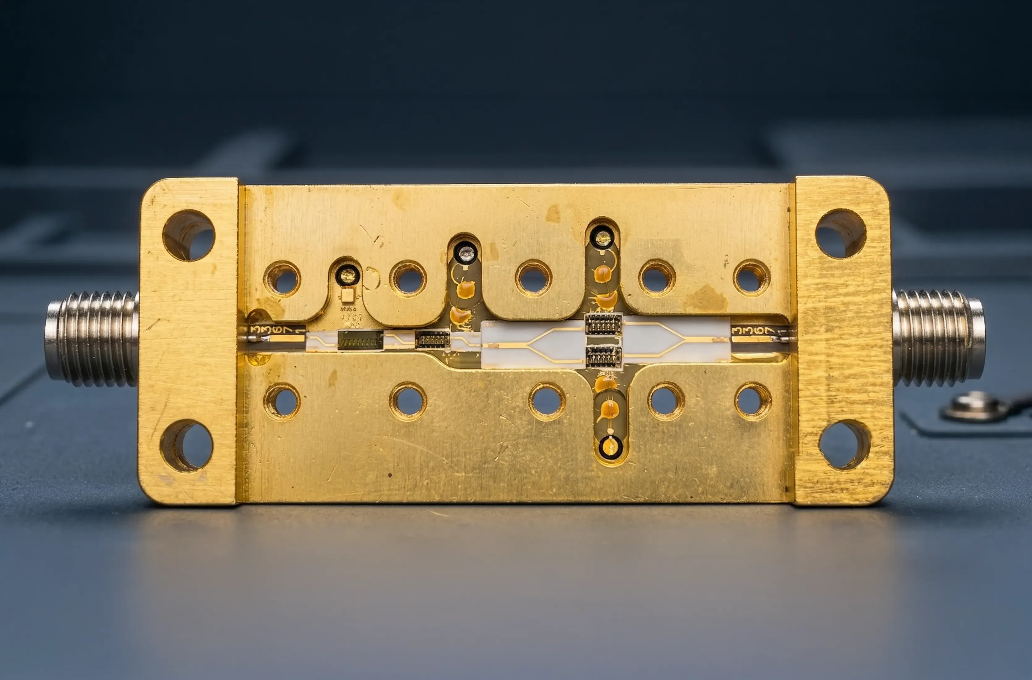
This section now shows the amplifier hardware directly, including the chip-and-wire construction that stands out as a meaningful capability differentiator. The important evaluation points remain connectoring, thermal behavior, and how the gain block fits into the larger chain.
System integration
Amplifiers are rarely the beginning of the architecture. They normally condition a path that already includes source, filtering, or frequency translation decisions.
Representative amplifier context
Packaging
Package style, RF interface, and control details should be chosen to fit the assembly around the amplifier rather than forcing the design into a generic form factor.
The safest path is to define the surrounding chain first, then choose the gain stage to match it.
Related solutions
Amplifiers are most effective when they are selected in the context of translation, source purity, and packaging constraints.
Linear Frequency Converters
Translation stages that often sit alongside gain conditioning and filtering.
Non-Linear Frequency Multipliers
Upstream extension stages that can benefit from clean drive and output conditioning.
Custom Integrated Microwave Assemblies
Subsystem packaging that combines amplification with the rest of the RF chain.
Next step
Tell Microsource about the band, level targets, and surrounding signal chain so the amplifier can be matched to the full application.