Representative ~5 fs RMS jitter
Representative measured jitter of about 5 fs over a 12 kHz to 20 MHz integration band positions this source as a high-performance timing option for demanding converter and array architectures.

LOW-JITTER MICROWAVE CLOCK SOURCE
A precision 10.24 GHz microwave clock source engineered for radar, EW, phased arrays, advanced satellite architectures, and converter-heavy digital RF systems where timing quality directly affects signal fidelity.
Representative measured performance includes about 5 fs RMS jitter, about -130 dBc/Hz phase noise at 10 kHz offset, and a low noise floor at higher offsets, all in a package oriented toward deployable use rather than lab-only form factors.
Product overview
A microwave clock source provides the timing reference that determines when signals are generated, sampled, and processed inside high-speed RF systems. At multi-GHz converter speeds, even femtosecond-level timing errors can directly degrade signal clarity, dynamic range, and spurious performance.
As architectures move toward direct RF sampling, digital beamforming, and higher-speed DAC/ADC paths, clock quality becomes a system-level limiter rather than a background specification.
System impact
Clock quality increasingly determines whether the rest of a high-speed RF architecture can realize its theoretical performance. Better timing translates into cleaner generation, cleaner sampling, and a more credible system budget.
Supports better ENOB and dynamic range in converter-centric architectures
Helps reduce system-level spurious behavior linked to timing quality
Improves signal fidelity for direct RF sampling and beamforming approaches
Bridges precision-clock performance with deployable subsystem constraints
The clock is not a universal fix by itself, but in the right architecture it can remove a major timing bottleneck.
Capabilities
The emphasis is on real timing performance in a microwave-domain output, not just a low-frequency reference specification.
Representative measured jitter of about 5 fs over a 12 kHz to 20 MHz integration band positions this source as a high-performance timing option for demanding converter and array architectures.
Designed around a nominal 10.24 GHz output frequency for systems that need a precision microwave-domain timing source rather than only a lower-frequency reference.
Leverages a stable 10 MHz external reference input and low-noise phase-locking techniques to translate a clean low-frequency reference into a high-frequency microwave clock.
Environmental targets and form factor are framed for real defense, aerospace, and mobile-system contexts, not just bench-top characterization.
Final architecture benefits should always be evaluated at the converter or subsystem level, where clock quality interacts with the rest of the signal path.
Applications
This product is most relevant wherever converter timing quality and microwave-domain clock integrity affect overall mission performance.
Supports architectures where converter timing and spectral cleanliness influence target detection, image quality, and coherent performance.
Useful in systems that require cleaner high-speed generation and sampling paths for microwave-domain signal creation and analysis.
Relevant to distributed timing and converter chains where clock quality can affect beam fidelity and overall array performance.
A fit for precision generation and sampling paths where timing quality and spectral purity both matter.
Well suited to DAC/ADC evaluation setups, characterization benches, and early integration prototypes where timing performance must be validated before subsystem commitment.
Can bridge the early evaluation use case and the longer-term need for hardware that fits real airborne, mobile, or ruggedized environments.
Representative performance
Representative electrical and environmental highlights drawn from current measured performance and released product collateral. Final values should always be confirmed against the approved configuration and test conditions.
| Parameter | Representative value |
|---|---|
| Core output | |
| Nominal frequency | 10.24 GHz |
| RF output differential power | 2 to 6 dBm into 100 ohms @ +25 C |
| Timing and spectral performance | |
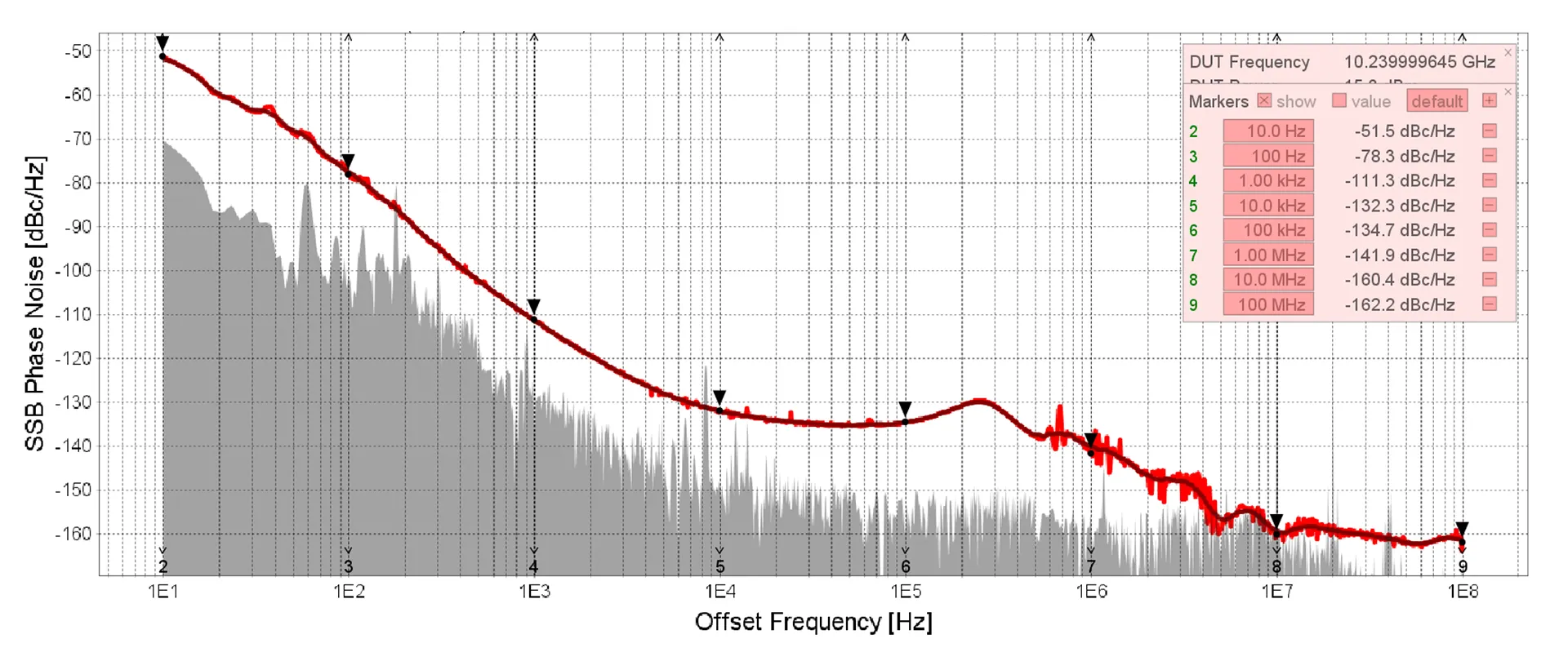
| RMS jitter | ~5 fs RMS integrated over 12 kHz to 20 MHz |
| Phase noise @ 1 kHz | -116 dBc/Hz |
| Phase noise @ 10 kHz | ~-130 dBc/Hz |
| Phase noise @ 100 kHz | Representative measured phase-noise roll-off |
| Phase noise @ 1 MHz | -146 dBc/Hz |
| Noise floor @ >=10 MHz offset | ~-165 dBc/Hz |
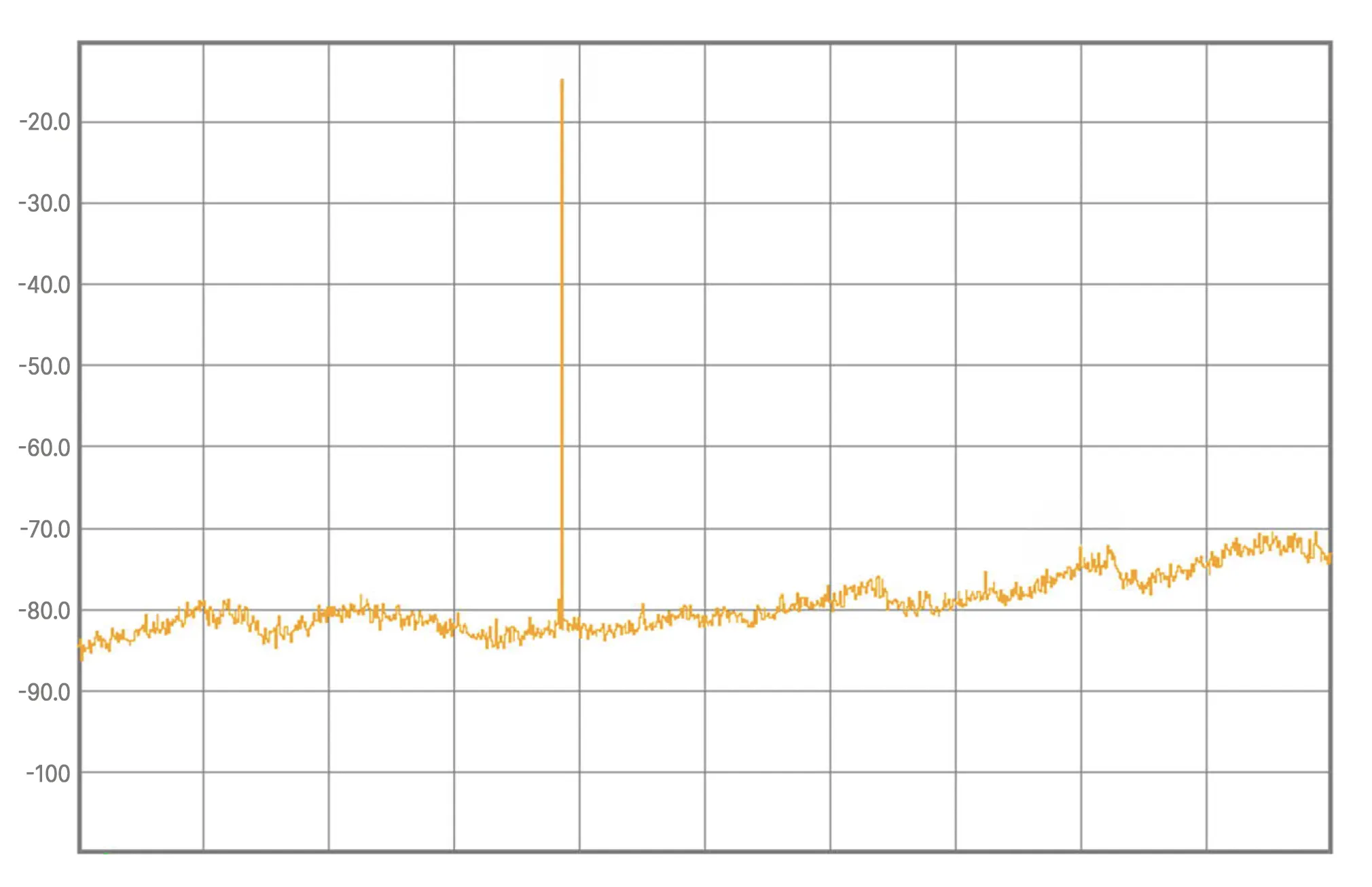
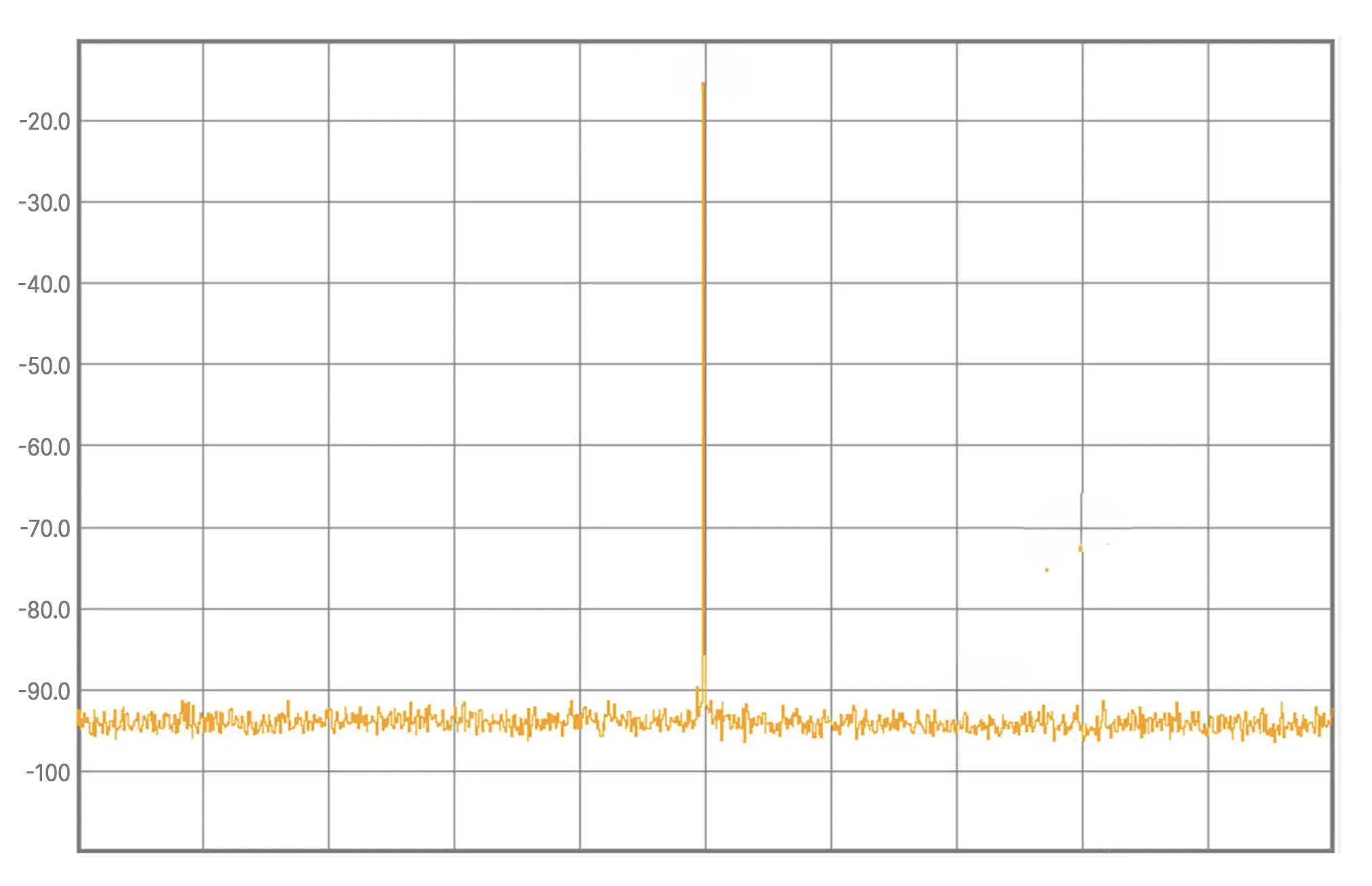
| Non-harmonic spurious | -70 dBc |
| Reference spurs | -60 dBc |
| Deployment context | |
| Operating temperature | -25 to +70 C specified; -40 to +85 C functional |
| Vibration | 16.8 G RMS, 5 Hz to 2 kHz |
| Shock | 20 G |
| PCA nominal size (without housing) | 5.0 x 2.2 x 1.25 inches |
Representative values shown for G-MCS-10-12-000 hardware. System benefit depends on architecture, integration point, and the converter or RF chain being clocked.
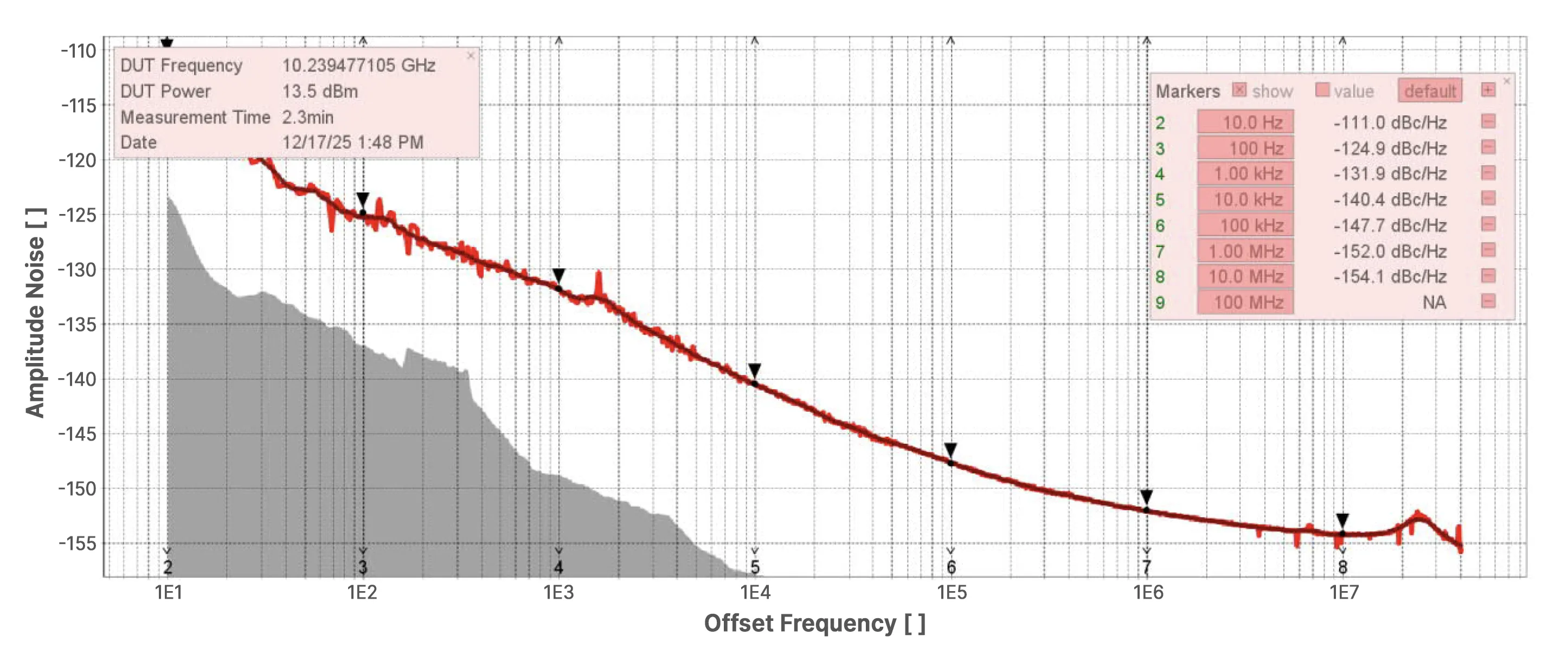
Measured data
Representative plots from current measured data help show how the clock source behaves across phase-noise, amplitude-noise, harmonic, and close-in spurious measurements. Values shown are representative of measured performance across recent hardware and test configurations.
Hardware
One of the main differentiators here is that the hardware is framed for system deployment, not just precision-bench use. That matters when the timing source has to survive temperature, vibration, packaging, and real integration constraints.
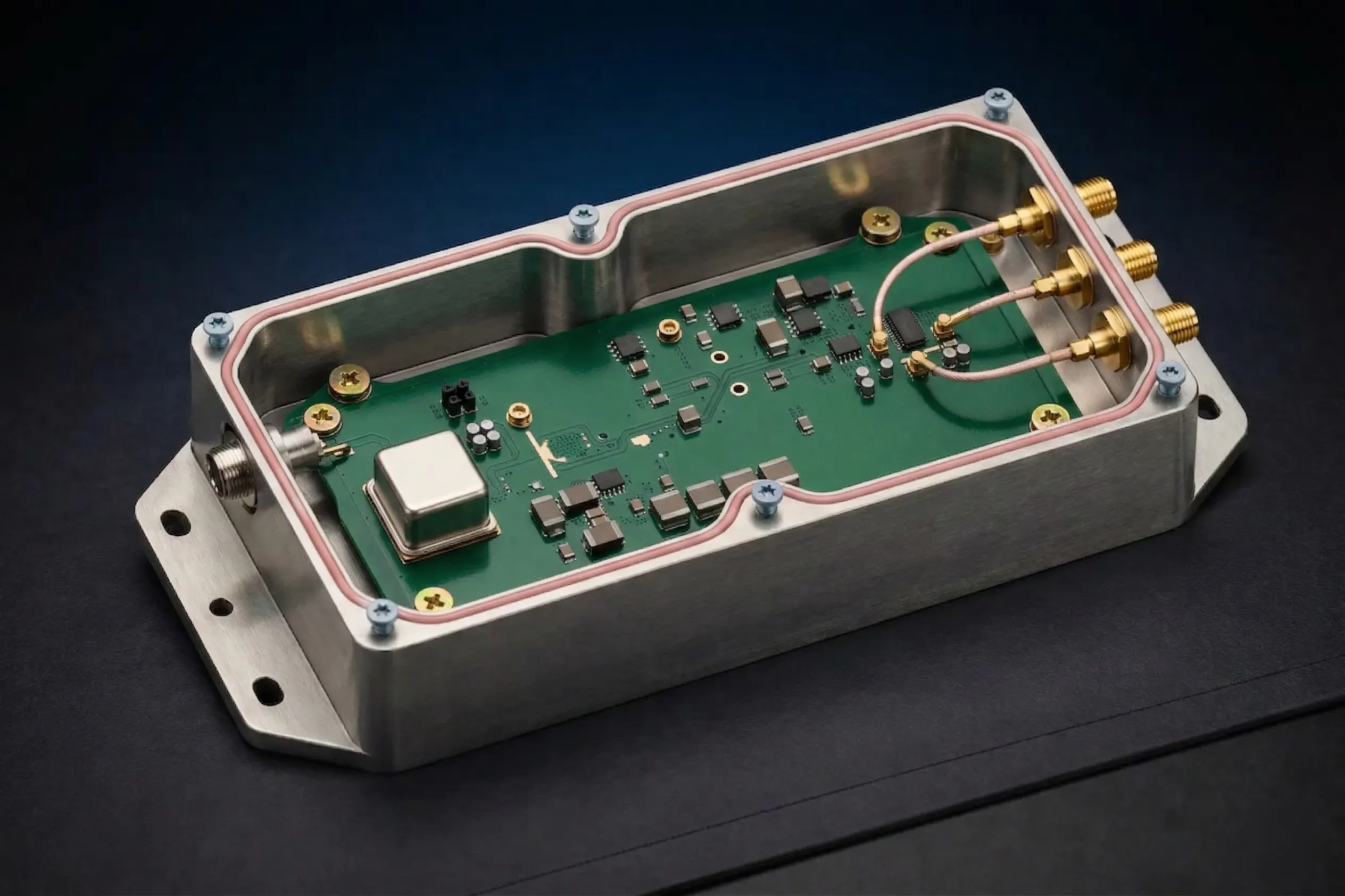
Architecture
At a high level, the architecture translates a stable low-frequency reference into a low-jitter microwave clock that can feed high-speed generation and sampling paths.
Representative microwave clock-source context
Integration notes
This kind of product is most successful when the integration point is defined clearly before the hardware is locked.
The closer this product sits to the actual converter or timing distribution problem, the more meaningful the performance evaluation becomes.
Related solutions
Clock quality lives inside a larger architecture, so this product naturally ties into source generation, translation, and integrated subsystem work.
Microwave Synthesizers
Phase-locked source hardware for LO and precision generation paths.
YIG Oscillators
Microsource oscillator heritage that informs low-noise microwave source design.
Custom Integrated Microwave Assemblies
System-level packaging for converter, clocking, and microwave subsystem integration.
Next step
Discuss your converter architecture, reference strategy, operating environment, and integration point with Microsource to determine whether this clock source is the right fit.