
MICROWAVE FREQUENCY SYNTHESIZERS
Microwave Frequency Synthesizers
Highly stabilized local oscillators—often locked to a crystal reference—with broad tuning bandwidth and low absolute phase noise.
Microsource frequency synthesizers are designed as LO sources for demanding RF subsystems. Implementations use either a high-performance VCO or one of our YIG-tuned oscillators (YTOs), depending on whether your system prioritizes settling agility or ultimate phase noise. The right choice balances multiplied reference noise inside the loop bandwidth against the free-running phase noise of the microwave source outside the loop bandwidth.
Signal generation
Engineered for demanding RF systems
Microsource synthesizers are built around either a high-performance VCO or a YTO, phase-locked to a crystal oscillator reference where the application requires it. Inside the PLL loop bandwidth, multiplied reference noise tends to dominate; outside the loop, the free-running phase noise of the microwave source matters more. That split drives real system tradeoffs among agility, absolute phase noise, step size, and attenuation control—especially when the synthesizer is acting as the LO in a conversion chain.
- VCO-based designs generally achieve faster frequency and phase settling; YTO-based designs trade speed for lower ultimate phase noise.
- Broad tuning bandwidth and programmable steps (e.g., 1 MHz steps on the documented 6–12 GHz example) support practical LO plans.
- Customers should define requirements in system terms: LO role, hop/settling budget, spectral mask, and environmental constraints—not bench-instrument marketing labels.
Capabilities
What we deliver
The fast-tuning VCO example below is published data for a representative configuration—not a generic placeholder.
Highly Stabilized LO Generation
Intended as highly stabilized local oscillators, commonly locked to a crystal reference for predictable long-term behavior and defined accuracy/aging.
Broad Tuning Bandwidth
Designed for wide tuning spans within a given band plan—illustrated by the 6.0–12.0 GHz fast-tuning VCO synthesizer example.
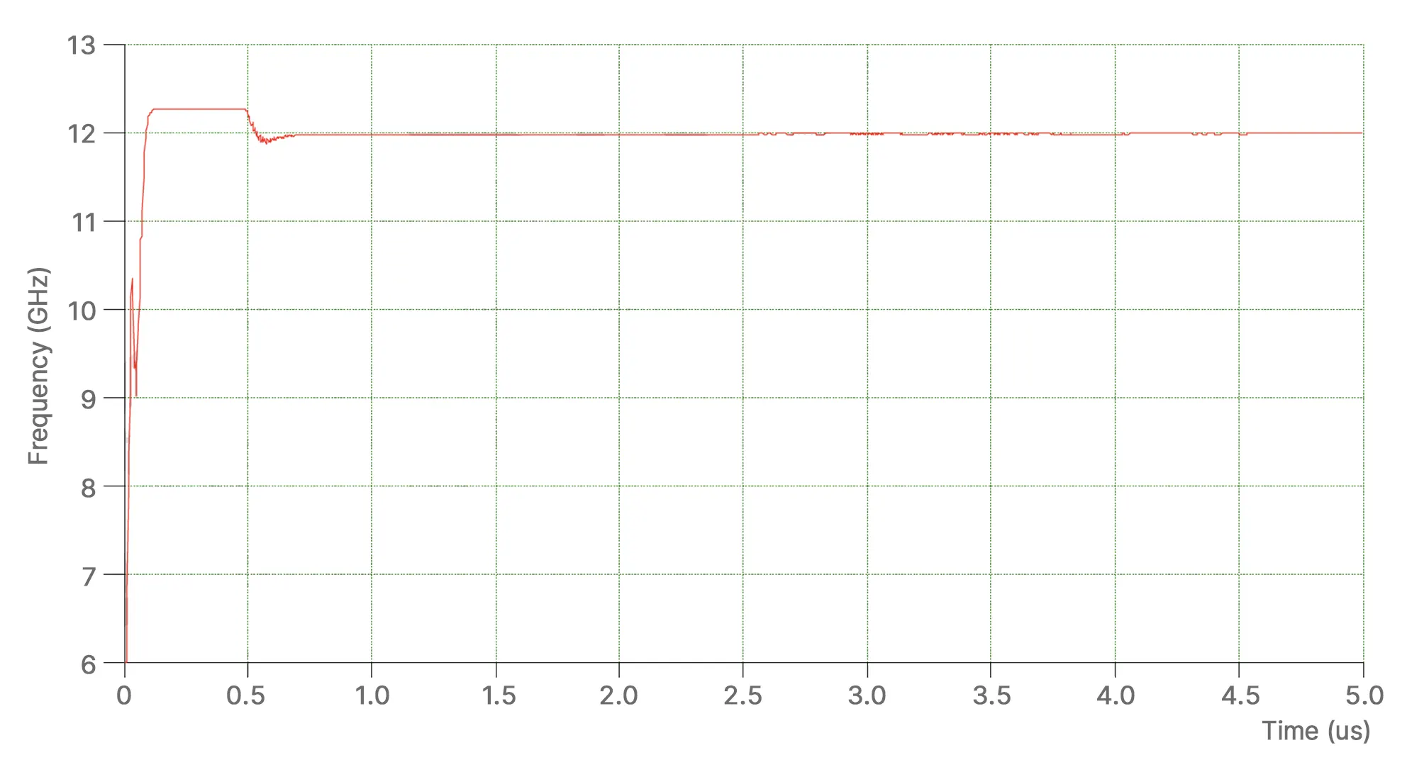
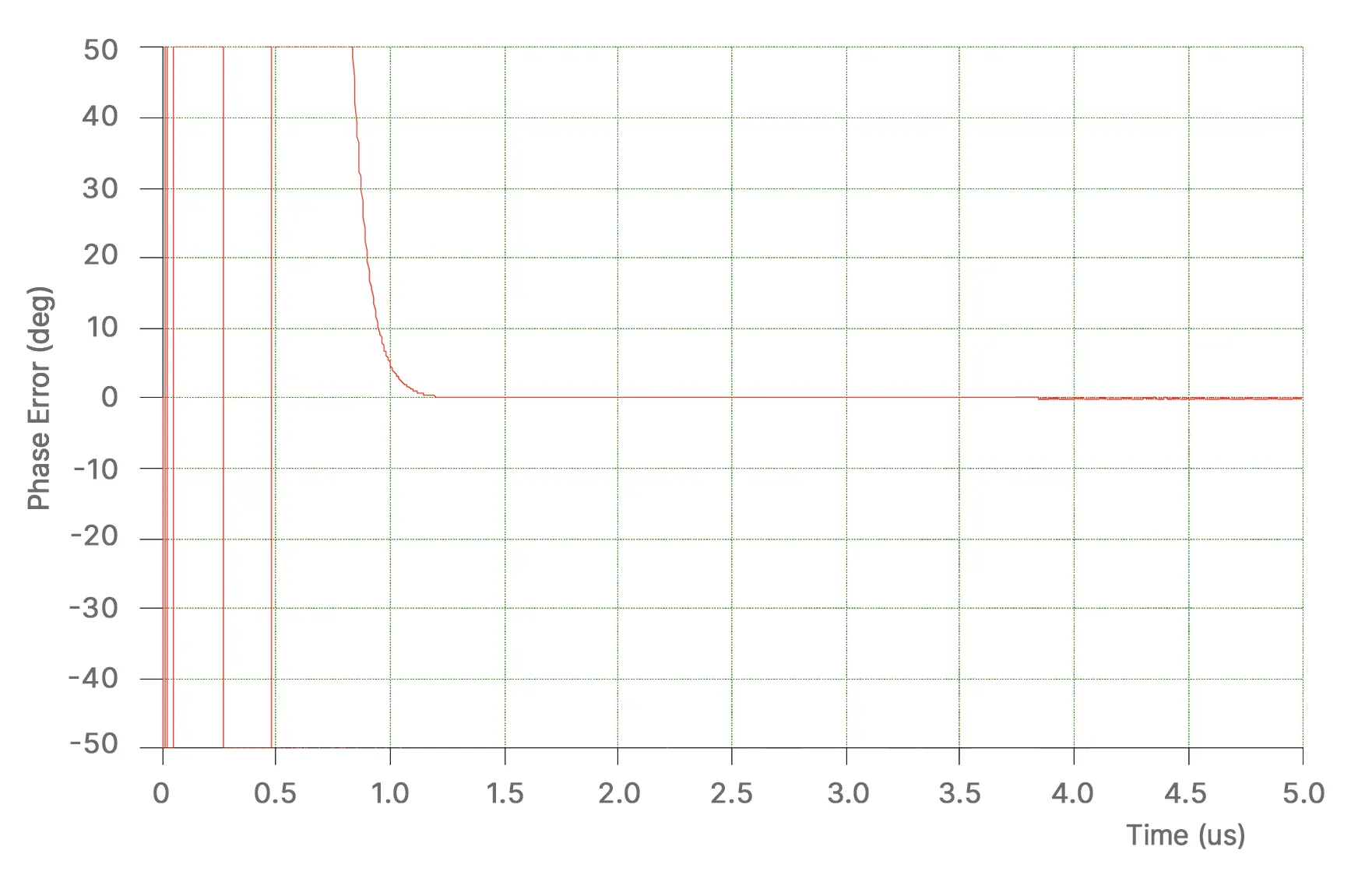
Fast Frequency and Phase Settling
On G-VSYN-06-12-000: frequency settling to within ±1 MHz in 1 µs; phase settling to within ±10° in 1 µs (published). VCO-based synthesizers are the path when agility is critical.
Low Absolute Phase Noise
Published absolute phase noise offsets for the 6–12 GHz example (e.g., −85 dBc/Hz @ 100 Hz through −105 dBc/Hz at higher offsets). YTO-based synthesizers target better ultimate phase noise when settling time can be relaxed.
Programmable Step and Attenuation Control
Documented example includes 1 MHz frequency steps and 0.5 dB attenuation steps (−30 to 0 dB) with 1 µs attenuation settling to 0.5 dB.
VCO or YTO Based Architectures
Microsource explicitly offers VCO-based and YTO-based synthesizers—the speed vs. ultimate phase noise tradeoff is the central design choice.
Architecture
Implementation approaches
Microsource frequency synthesizers are realized with either a high-performance VCO or one of our YTOs, phase-locked as the application requires. The sections below reflect that split.
VCO-based synthesizers
VCO-based synthesizers generally exhibit faster settling time—suited when frequency and phase agility are primary. The tradeoff is ultimate phase-noise performance relative to a YTO-based approach for comparable band and control complexity.
YTO-based synthesizers
YTO-based synthesizers are positioned for lower ultimate phase noise, building on Microsource’s YIG-tuned oscillator heritage. Settling is slower than typical VCO-based implementations—acceptable when the noise budget dominates the hop-time budget.
Loop optimization / phase-locked architecture
Performance depends on how reference noise and source noise partition: multiplied reference noise tends to dominate inside the PLL loop bandwidth, while the free-running phase noise of the microwave source is more visible outside the loop bandwidth. Loop bandwidth and frequency plan choices should follow system-level analysis—not a one-size default.
Model numbering
Designations follow G-ASYN-XX-YY-ZZZ, where A indicates V (VCO-based) or Y (YTO-based), XX is the lowest output frequency in GHz, YY is the highest output frequency in GHz, and ZZZ is a configuration suffix.
G-VSYN-06-12-000 — example: 6–12 GHz VCO-based fast tuning synthesizer
Applications
Local oscillator roles
Synthesizers in this family are positioned as highly stabilized LO sources for microwave subsystems—not general-purpose bench signal generators.
Highly stabilized local oscillators
LO generation with crystal-referenced stability, defined accuracy/aging, and controlled spectral behavior.
Radar systems
LO chains and exciter paths where tuning range, settling, and phase noise must match mode-to-mode radar requirements.
Electronic warfare
Agile LO behavior when VCO-based settling is required; YTO-based paths when spectral purity drives the architecture.
SIGINT / ISR
Stable, programmable LO coverage for collection front ends and analysis signal chains.
Frequency conversion chains
Drives mixers and converters as the referenced tone that sets system IF/LIF plans—paired naturally with Microsource converters and multipliers.
Aerospace / defense microwave subsystems
Packaging, power, and temperature extremes (see representative example: −40 to +85 °C) aligned to deployed hardware.
Advanced test systems
Subsystem-level test integration where the LO must mirror production architecture—not a generic lab signal generator use case.
Configurations
Representative configurations
VCO vs. YTO synthesizer implementations, reference discipline, and packaging for harsh environments—not an exhaustive model matrix.
Fast-tuning VCO-based synthesizers
Documented example G-VSYN-06-12-000 (6–12 GHz) illustrates fast settling and published RF/attenuation control.
Low-phase-noise YTO-based synthesizers
YTO paths for better ultimate phase noise at the expense of settling time versus VCO-based designs.
Crystal-referenced LO subsystems
Highly stabilized LOs locked to a crystal oscillator reference—with stated accuracy and aging when an internal reference is used.
Integrated synthesizer / attenuator assemblies
The published 6–12 GHz example includes defined RF output power and programmable attenuation with specified settling.
Custom screened harsh-environment configurations
Microsource supports screening and environmental options consistent with defense/aerospace programs—details are quote-specific.
Packaged assemblies with +28 V supply options
Representative packaging includes example exterior supply at +28 V and defined input voltage range (16–40 V) on the documented example.
Representative configuration
G-VSYN-06-12-000 — fast tuning synthesizer
Representative published data for MICROSOURCE FAST TUNING SYNTHESIZER G-VSYN-06-12-000 (6.0–12.0 GHz, VCO-based). Other VCO- and YTO-based implementations are available—final numbers follow the approved datasheet for your configuration.
| Parameter | Value |
|---|---|
| Identification | |
| Model | G-VSYN-06-12-000 |
| Description | Microsource fast tuning synthesizer (VCO-based) |
| Frequency & reference | |
| Frequency range | 6.0 to 12.0 GHz |
| Frequency accuracy (internal reference @ +25 °C) | ±2 ppm |
| Frequency aging (internal reference) | 5 ppb/day |
| Frequency step size | 1 MHz |
| Settling | |
| Frequency settling time (to within ±1 MHz) | 1 µs |
| Phase settling time (to within ±10°) | 1 µs |
| RF output & attenuation | |
| RF output power | 7 dBm |
| Attenuation range | −30.0 to 0 dB |
| Attenuation step size | 0.5 dB |
| Attenuation settling time (to 0.5 dB) | 1 µs |
| Phase noise (absolute) | |
| Phase noise @ 100 Hz offset | −85 dBc/Hz |
| Phase noise @ 1 kHz offset | −105 dBc/Hz |
| Phase noise @ 10 kHz offset | −105 dBc/Hz |
| Phase noise @ 100 kHz offset | −105 dBc/Hz |
| Phase noise @ 1 MHz offset | −105 dBc/Hz |
| Spurious & harmonics | |
| RF output spurious | −60 dBc |
| RF output harmonics (Pout = 0 dBm) | −25 dBc |
| RF output sub-harmonics | −80 dBc |
| Power & environment | |
| Input voltage range | 16 to 40 V |
| Input current @ +28 V | 0.5 A |
| Operating temperature range | −40 to +85 °C |
Representative example only. Additional VCO-based and YTO-based synthesizer implementations are available from Microsource. Final performance depends on architecture, frequency plan, reference, control interface, and application requirements.
Measured data
Typical performance (representative figures)
Catalog-backed measured plots for the representative 6.0-12.0 GHz fast-tuning synthesizer, including phase noise, settling behavior, and passband RF power.
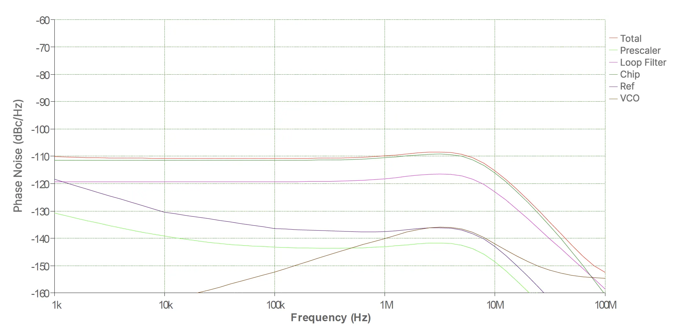
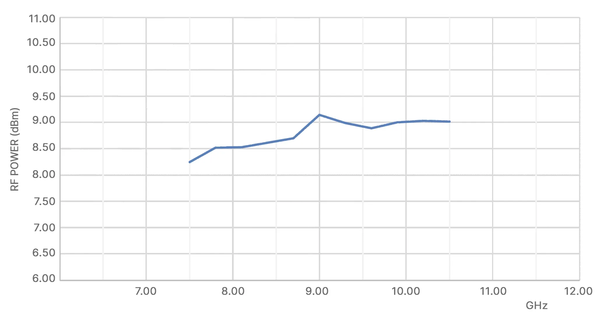
Representative measurements for G-VSYN-06-12-000 from the MSI catalog. Final values still depend on architecture, reference, and approved program configuration.
Packaging
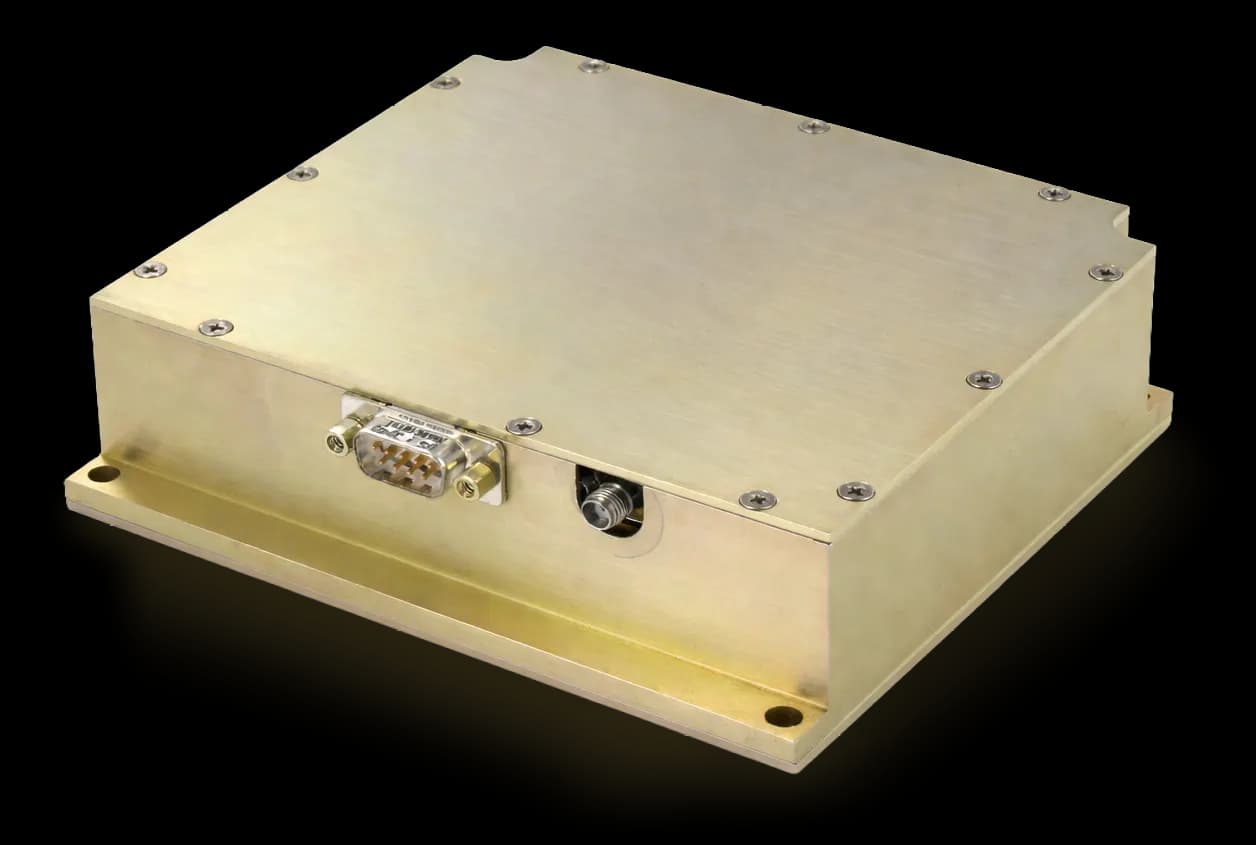
Mechanical & materials
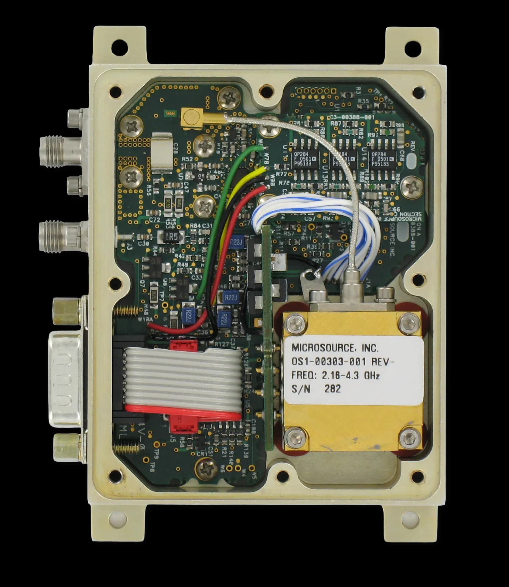
Representative construction for the assembly—use for planning interfaces and environmental design; exact configuration may vary by program.
- Printed circuit board / packaged assembly views document mechanical context.
- Representative dimensions: 7.0" L × 5.0" W × 0.50" H.
- Outer shield: aluminum alloy 6061, chemical conversion coated per MIL-DTL-5541F.
- Gasket: silver/aluminum impregnated silicone rubber.
- RF connections: SMA, SMPM, TNC, or equivalent.
- DC pins: soft electroless gold over Kovar (Fe-Ni-Co alloy) or equivalent.
- Example exterior packaging shown with +28 V supply.
Why Microsource
YTO heritage, VCO agility, system-level optimization
Microsource brings established YIG-tuned oscillator heritage and high-performance VCO synthesizer capability—so the documented VCO vs. YTO tradeoff is a real design axis, not marketing language. We support harsh-environment packaging, custom screening, and loop-level optimization so settling time, absolute phase noise, and control granularity match your LO requirements.
Related solutions
Adjacent product families
Synthesizers tie directly to oscillators, conversion, multiplication, and integrated assemblies in the signal chain.
- YIG OscillatorsYTO products used in YTO-based synthesizer paths.
- Frequency ConvertersUp/down conversion driven by stable LOs.
- Frequency MultipliersReference and chain extension around synthesized tones.
- DRO OscillatorsFixed references and alternate LO building blocks.
- Integrated Microwave AssembliesMulti-function RF assemblies and subsystem integration.

NEXT STEP
Discuss frequency plan, architecture, and screening
Share your LO role, tuning band, settling budget, phase-noise mask, and platform environment—we will align VCO- vs. YTO-based options and control interfaces to realizable implementations.