Frequency translation
Moves the signal from a lower-frequency source or IF path into the intended RF output band.
LINEAR UP-CONVERTERS
Microsource linear up-converters translate lower-frequency IF or drive signals into higher RF bands for transmit chains, exciters, and other microwave applications.
Current wide-band coverage includes datasheet-backed 2.0-20.0 GHz hardware such as G-WBTX-02-20-000, built around a 3.10-4.10 GHz IF input and 1.0 GHz instantaneous bandwidth.
Product overview
Translates a lower-frequency IF or drive signal into the higher RF band where the system needs to radiate, stimulate, or otherwise use the energy.
Typically in exciter or transmit-side chains where the translated output must be managed alongside gain, filtering, and final packaging decisions.
Signal translation
Up-conversion is useful when the system starts with a lower-frequency source or IF path and needs to place energy into a higher microwave band for transmission or stimulation.
Translates IF or drive signals into a higher output band
Supports transmit and exciter chain architecture
Works best when spectral cleanliness and gain plan are defined up front
Often paired with filtering or amplification inside a broader subsystem
Final frequency coverage and conversion behavior are program-specific and should be matched to the approved design.
Capabilities
The page is framed around practical system behavior: translation, output control, and clean interface integration.
Moves the signal from a lower-frequency source or IF path into the intended RF output band.
Useful when the converter feeds an exciter, driver, or final transmit path inside a larger system.
Can be paired with filtering or conditioning stages when the output spectrum needs to stay controlled.
Mechanical and electrical interfaces should follow the surrounding subsystem, not the other way around.
If the output band is shared with sensitive adjacent systems, plan the filtering and gain structure alongside the converter.
Applications
Up-converters are best thought of as one step in a larger transmit or exciter architecture.
Places drive energy into the desired transmit band while keeping the signal chain organized around the platform plan.
Supports frequency translation for transmit or stimulation paths in electronic warfare systems.
Useful when an IF source must be translated into an operational RF band.
Handy for bench or validation setups that need translated output in a controlled band.
Representative performance
These values are taken from current released collateral for the wide-band G-WBTX-02-20-000 platform. They give teams a concrete transmit-side reference instead of the broader generic guidance that was previously on this page.
| Parameter | Representative value |
|---|---|
| Signal plan | |
| IF input frequency | 3.10-4.10 GHz |
| RF output frequency | 2.0-20.0 GHz overall; split as 2.0-12.35 GHz and 12.25-20.0 GHz |
| Channel bandwidth (IBW) | 1.0 GHz |
| Nominal IF input level | -4 dBm |
| Gain and cleanliness | |
| Conversion gain | 10 dB |
| RF output P-1dB | 10 dBm |
| Attenuation range | -60 to 0 dB in 0.5 dB steps |
| Attenuation settling time | 1 us to within 0.5 dB |
| Channel bandwidth flatness | 6.0 dB pk-pk |
| RF output spurious | -60 dBc to 18 GHz, -50 dBc from 18-20 GHz |
| RF output IMD | -50 dBc at POUT = -10 dBm, 1 MHz carrier spacing |
| Residual phase noise | -130 dBc/Hz at 100 MHz offset |
| Interfaces and environment | |
| LO drives | LO1: 12.75-13.35 GHz, LO2: 7.5-10.5 GHz, both at -2 to +2 dBm |
| Input / output SWR | 2.0:1 on RF, IF, and LO ports |
| Input voltage / current | 16-40 V, 0.5 A typical at +28 V |
| Operating temperature | -40 to +85 C |
Values shown for G-WBTX-02-20-000 hardware. Final output band plan, LO strategy, attenuation setting, and packaging details should still follow the approved configuration.
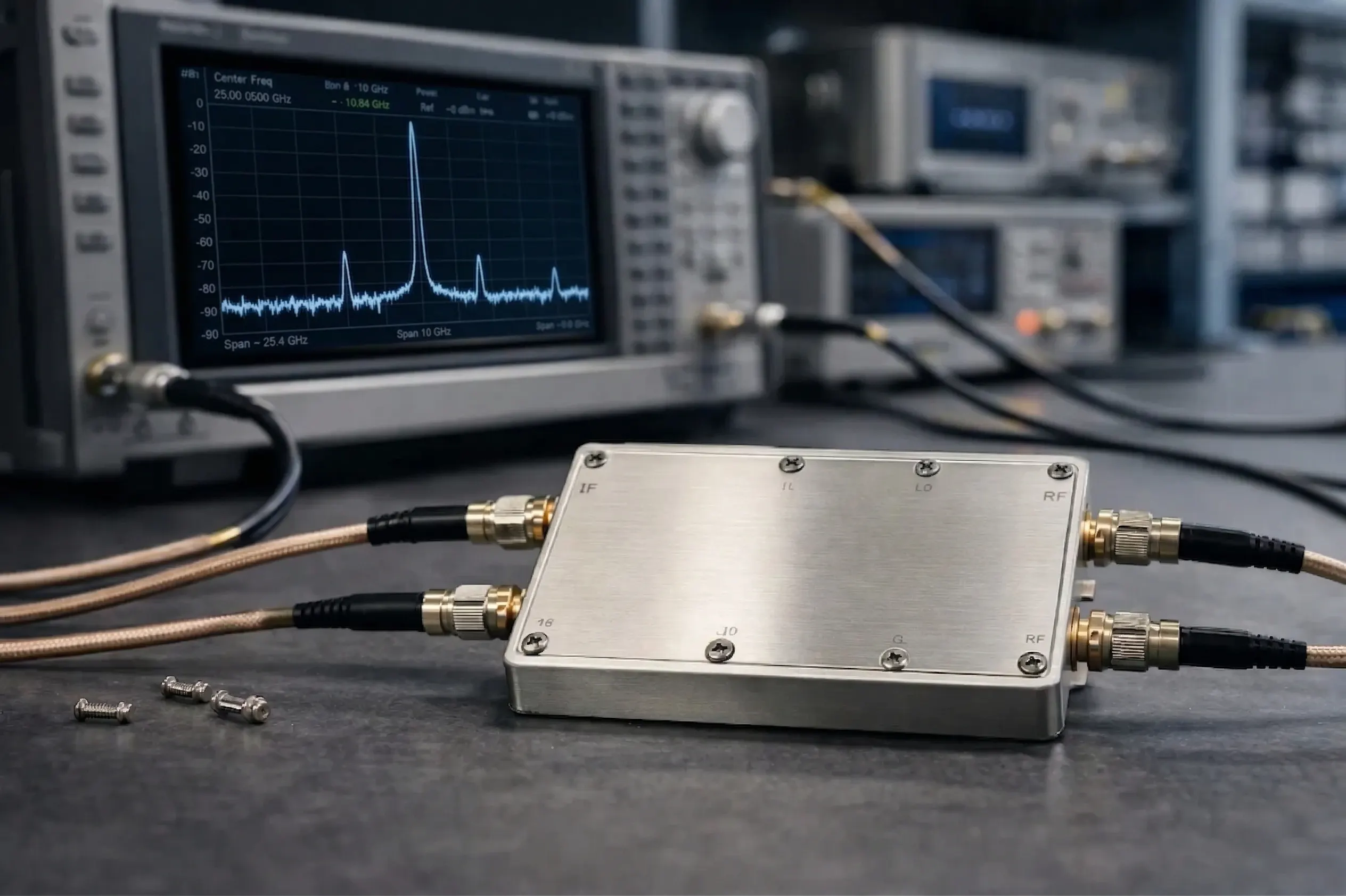
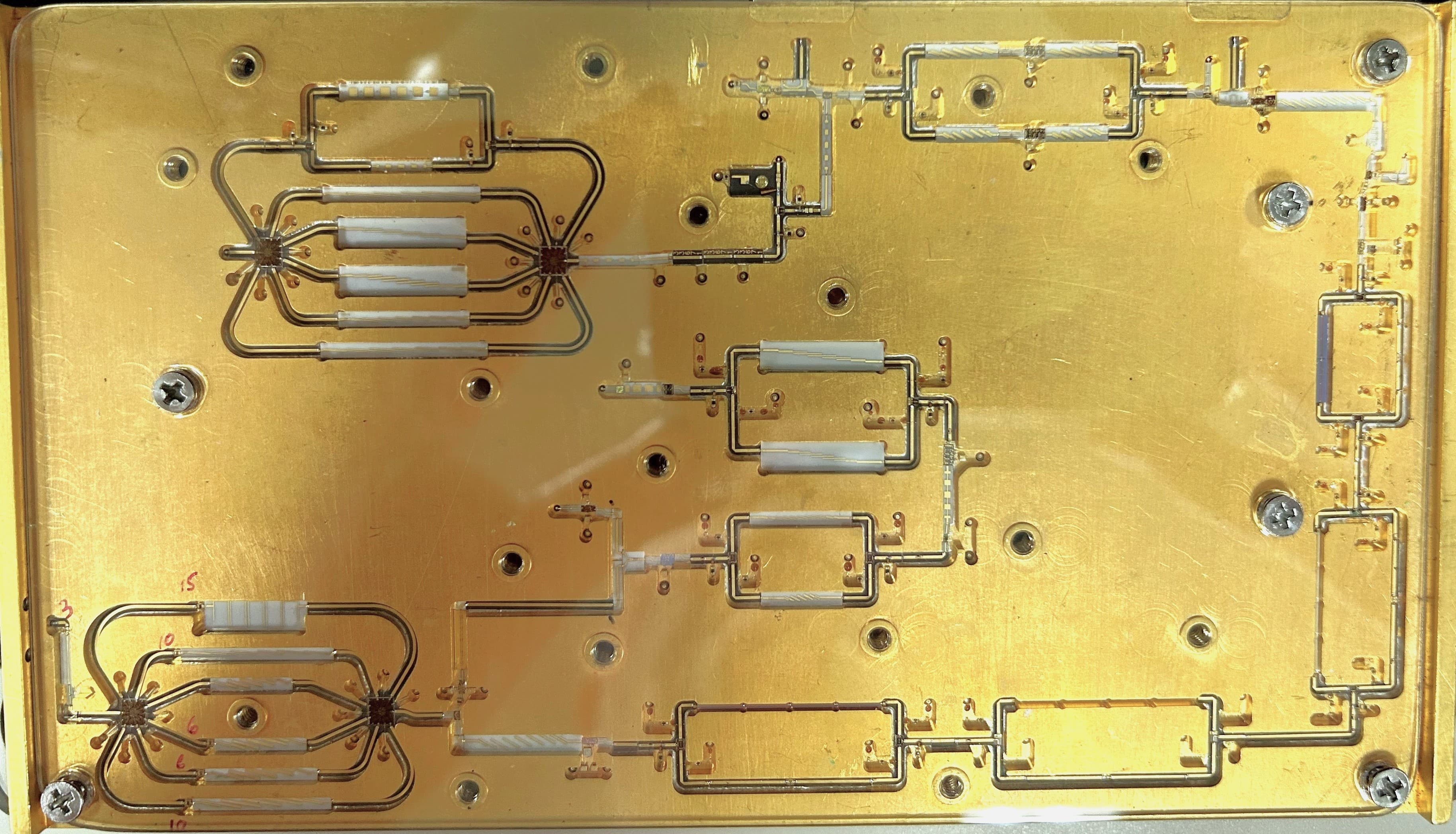
Hardware
This page now points at the current wide-band module family rather than only a lab-context image. The present hardware shares the same core packaged approach as the companion down-converter platform.
System integration
Up-converters normally sit between a lower-frequency source or IF path and the rest of the output chain. Their success depends on how cleanly they hand off into filtering, amplification, and final transmission.
Representative up-conversion context
Packaging
Converter packaging should align with the platform's band plan, interface expectations, and environmental requirements.
Converter performance is easiest to judge when the source, load, and operating environment are all known.
Related solutions
Up-converters are usually selected together with the source, filter, and packaging strategy around them.
Microwave Frequency Synthesizers
Stable sources that can provide the translated signal path input.
Non-Linear Frequency Multipliers
Useful when the frequency plan needs extension before or after translation.
Custom Integrated Microwave Assemblies
Useful when the converter must be packaged with the rest of the chain.
Next step
Share the source, target band, and interface requirements so Microsource can evaluate the up-conversion path in context.