Receiver-side translation
Moves microwave energy into an IF or analysis band that is easier to process downstream.
LINEAR DOWN-CONVERTERS
Microsource linear down-converters translate microwave energy into a lower-frequency IF or analysis band for receiver, monitoring, and test paths.
Current wide-band coverage includes datasheet-backed 2.0-18.0 GHz hardware such as G-WBRX-02-18-000, built around a 3.10-4.10 GHz IF output and 1.0 GHz instantaneous bandwidth.
Product overview
Moves received microwave energy into a lower-frequency IF or analysis band where the rest of the chain can process it more effectively.
Most often in radar, SIGINT, monitoring, or receive-side architectures where the translated output needs to remain clean and useful to the downstream stages.
Signal translation
Down-conversion moves a microwave signal into a band where it can be analyzed, filtered, digitized, or otherwise processed more effectively.
Translates higher-frequency input into a practical IF or analysis band
Supports receiver, monitoring, and measurement chains
Can be paired with filtering or gain conditioning as needed
Works best when the surrounding signal plan is defined early
Actual frequency coverage and performance expectations depend on the approved band plan and configuration.
Capabilities
The role of this page is to help engineers and stakeholders understand how the receiver path is translated and why that matters.
Moves microwave energy into an IF or analysis band that is easier to process downstream.
A controlled translation stage helps preserve the usefulness of the received signal.
Can be matched to the channel plan, gain structure, and mechanical envelope of the receiver system.
Often works best as part of a packaged receiver or monitoring assembly rather than as a loose module.
Define the receiver objective first, then choose the down-converter to support that objective cleanly.
Applications
Down-converters are natural fits for receiver and monitoring applications that need translated output in a manageable band.
Translates high-frequency returns into an IF path where further processing can happen.
Supports analysis systems that need to move signals into a band suited for detection or digitization.
Useful in collection and analysis paths where broad coverage and signal integrity matter.
Helps bench and lab setups translate signals into a more convenient analysis band.
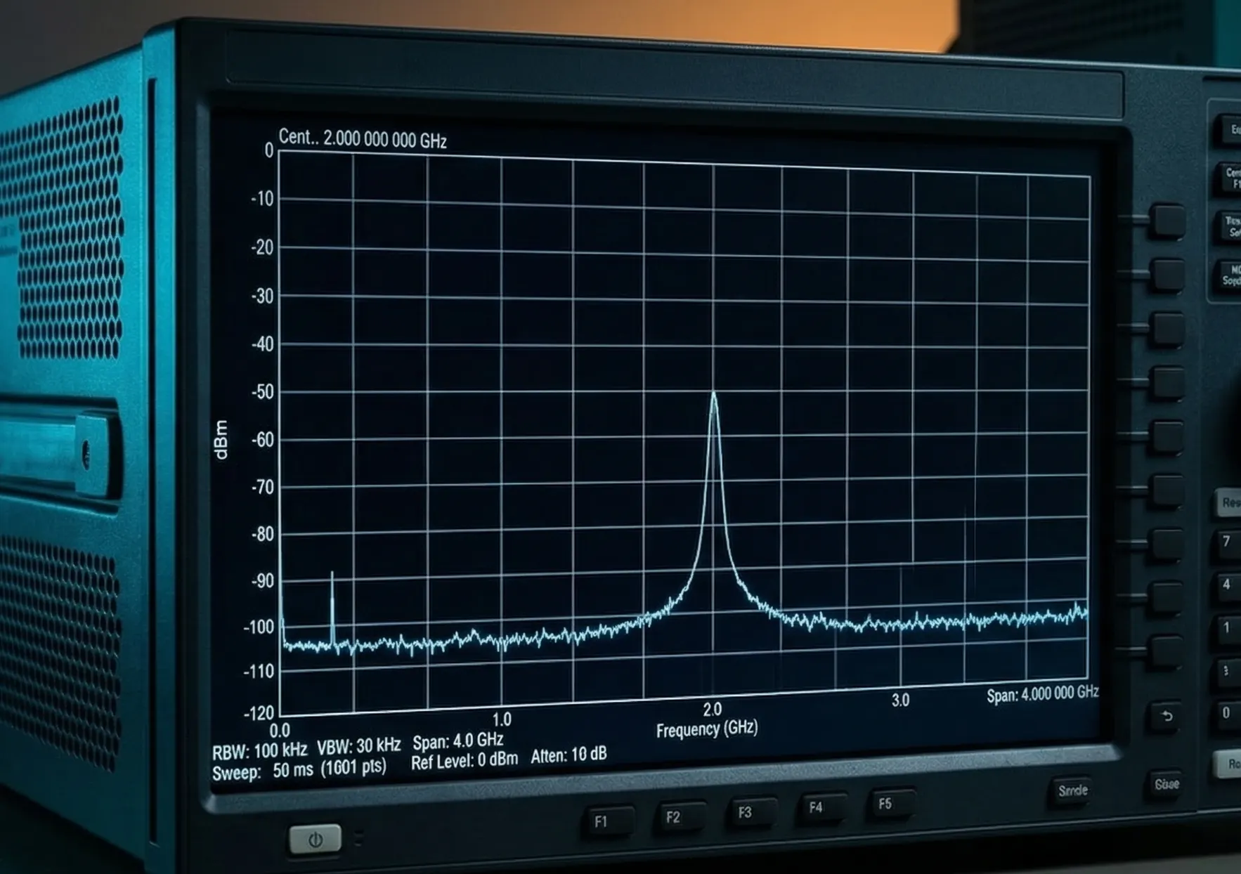
Representative performance
These values are taken from current released collateral for the wide-band G-WBRX-02-18-000 platform. They give engineers a concrete reference point for RF coverage, translated IF behavior, gain, and receiver-side signal quality.
| Parameter | Representative value |
|---|---|
| Signal plan | |
| RF input frequency | 2.0-18.0 GHz overall; split as 2.0-12.35 GHz and 12.25-18.0 GHz |
| IF output frequency | 3.10-4.10 GHz |
| Channel bandwidth (IBW) | 1.0 GHz |
| Nominal RF input level | -40 dBm |
| Gain and cleanliness | |
| Conversion gain | 40 dB |
| Attenuation range | -60 to 0 dB in 0.5 dB steps |
| Attenuation settling time | 1 us to within 0.5 dB |
| Channel bandwidth flatness | 6.0 dB pk-pk |
| Noise figure | 12 dB |
| IF output spurious | -60 dBc |
| IF output IMD | -50 dBc at POUT = -10 dBm, 1 MHz carrier spacing |
| IF output P-1dB | 10 dBm |
| Residual phase noise | -130 dBc/Hz at 100 MHz offset |
| Interfaces and environment | |
| LO drives | LO1: 12.75-13.35 GHz, LO2: 7.5-10.5 GHz, both at -2 to +2 dBm |
| Input / output SWR | 2.5:1 RF/IF, 2.0:1 on LO ports |
| Input voltage / current | 16-40 V, 0.45 A typical at +28 V |
| Operating temperature | -40 to +85 C |
Values shown for G-WBRX-02-18-000 hardware. Final band plan, LO strategy, attenuation setting, and packaging details should still be confirmed against the approved configuration.
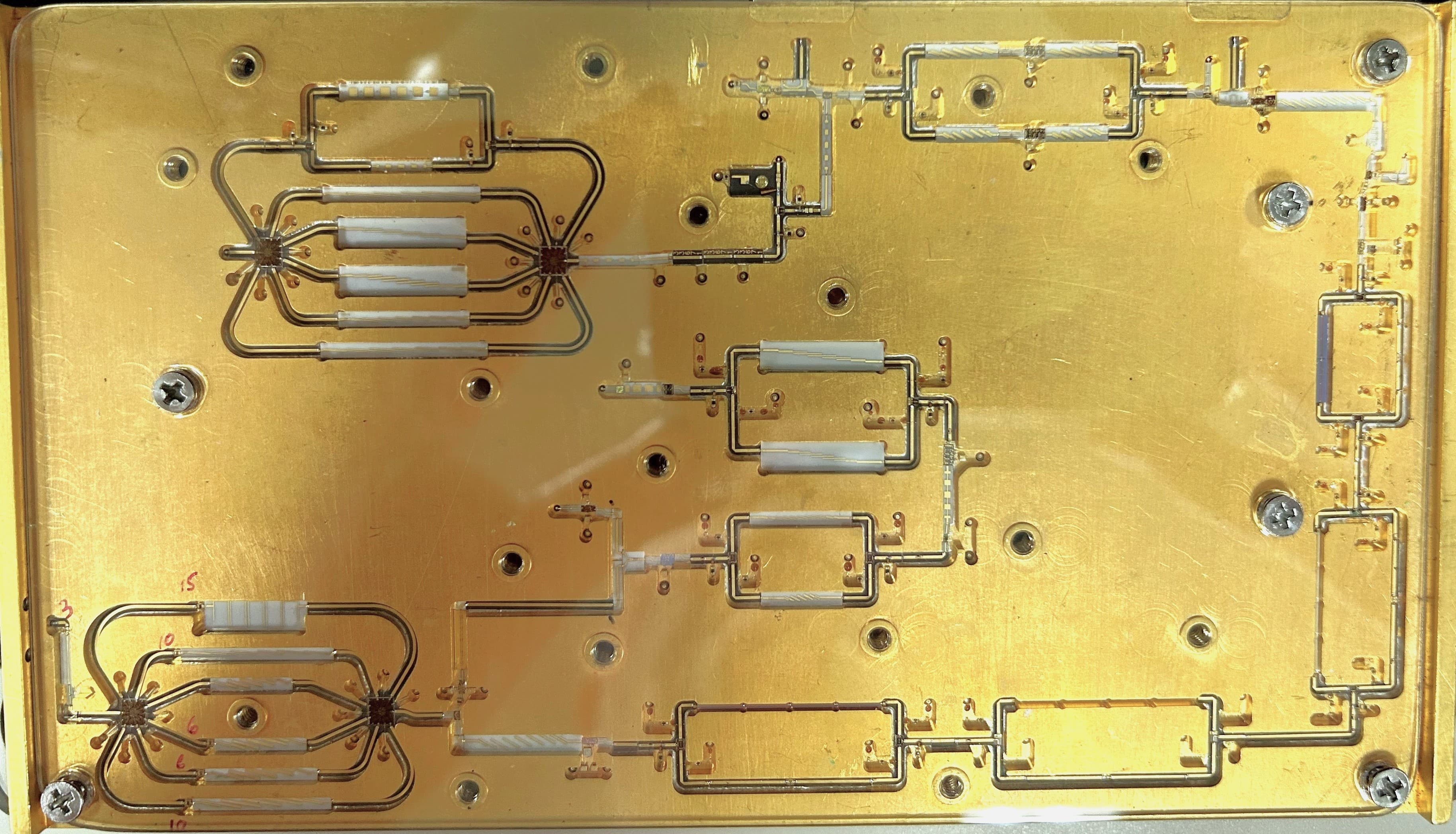
Hardware
This page now reflects the current wide-band hardware rather than a generic receiver placeholder. The package shown here is representative of the present G-WBRX-02-18-000 mechanical approach.
System integration
Down-converters sit between the incoming microwave path and the lower-frequency analysis or receiver stages. Their value comes from making the rest of the receiver easier to use without losing the signal’s usefulness.
Representative down-conversion context
Packaging
The package should follow the receiver architecture, control plan, and mechanical constraints of the platform.
The best down-converter is the one that makes the rest of the receiver easier to use.
Related solutions
Down-converters usually appear alongside sources, filters, and integrated subsystem packaging.
Linear Frequency Converters
Broader conversion portfolio that includes both transmit and receive use cases.
YIG Tuned Filters
Useful when receiver-side selectivity or interference suppression is required.
Custom Integrated Microwave Assemblies
Custom packaging for receiver-side translation and conditioning paths.
Next step
Share the input band, IF target, and integration constraints so Microsource can evaluate the down-conversion path in context.